|
Analytical Study of EM Waves in Mu ltilayered Cylinder Filled With Double Negation and Positive Materials
Janardan Prasad Singh and Ashok Kumar Singh
University Department of Physics, VKSU, Ara, Bihar, India HNK Inter College, Ara, Bihar, India
Abstract
In this paper, a multilayered cylinder filled with double negative (DNG) material and double positive (DPS) material is studied. General formulas of electromagnetic fields in each region are derived using the eigenfunction expansion method. The expansion coefficients are determined by a recursive system that is derived from boundary conditions at the multiple interfaces. The reflection by a cylinder with ( e 0 ,- µ 0 ) (where e 0 and µ 0 denote the permittivity and permeability in free space, respectively) is found to be quickly diminished with its electric size. For an infinite line source, the image propert y is observed when the radius of this cylinder is much larger than the wavelength. The distributions of electromagnetic fields are presented when a line so urce is placed near a two- layered cylinder alternately filled with DNG and DPS material. Numerical results confirm that the developed formulas are suitable to analyze the other multilayered cylindrical structures with DNG and DPS materials.
1. Introduction
The permeability and permittivity of materials are two fundamental parameters of the constitutive relations which determine how the media interact with electromagnetic (EM) waves propagating in the materials. In 1968, Veselago [1968] theoretically studied wave characteristics in a special medium whose permittivity and penneability are both negative simultaneously. These hypothetical materials exhibit a left-handed rule defining the polarizations of electric and magnetic fields and the propagation vector constant and the media are thus referred to as left- handed materials (LHM) in literature [Chen et al., 2004; Grbic and Elefiheriades, 2004; Katsarakis et al., 2004; Ziolkowski and Kipple, 2003; Panoiu and Osgood, 2003; Kuznuiak and Maradudin, 2002; Markos and Soukoulis, 2002; Yao et al., 2005a, 2005b]. The double negative (DNG) material has shown special optical properties, and could lead to a perfect lens [Pendry, 2000; Zhang et al., 2002; Pendry and Ra,nakrishna, 2003; Pendry, 2003; Ye, 2003; .Rainakrishna and Pendry, 2004]. For EM waves propagating through a stratified DNG medium, reflection and refraction of the waves
2. Formulations
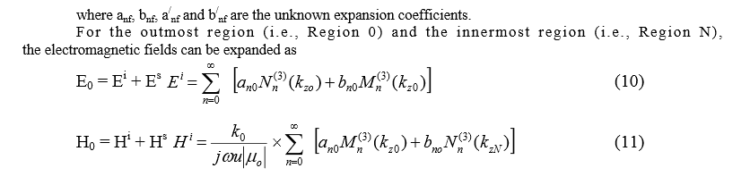
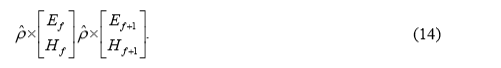
We consider an N-layered infinitely long cylinder situated in free space ( ε 0 , μ 0 ), as depicted in Figure 1. In each layer, it is f illed with DNG or DPS homogeneous material of different permittivity and permeability. In the following analysis the time dependence, is suppressed. The permittivity and permeability of material in region f ( f = 0,...N) are denoted as follows: tj e ω − f f u εε = (1) |
|
were formulated by Kong [2002]. The objective of this paper is to extend the existing application from planar structures to cylindrical structures, so as to gain more insight into the hybrid effects of metamaterials and cylindrical curvature. Potential applications of the results in this work include the conformal antenna radome analysis and design, two-dimensional microwave and optical imaging, etc. In this paper, we first derive a general formula of EM fields in all regions of a multilayered cylinder with DNG and DPS materials in this paper. The eigenfunction expansion method is applied to express the EM fields in this structure. To verify our fo rmulations and validate our analysis, the distant scattering sections for a two- layered cylinder with double positive medium are first shown. Next, we consider some special cases to characterize the DNG materials. The first example that we consider is a diel ectric cylinder with (- ε 0 ,- μ 0 ) which has a refractive index of n = -1.
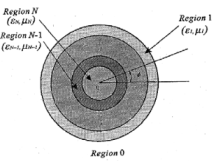 Figure 4.1. Geometry a multilayered cylinder with different materials. Figure 4.1. Geometry a multilayered cylinder with different materials.
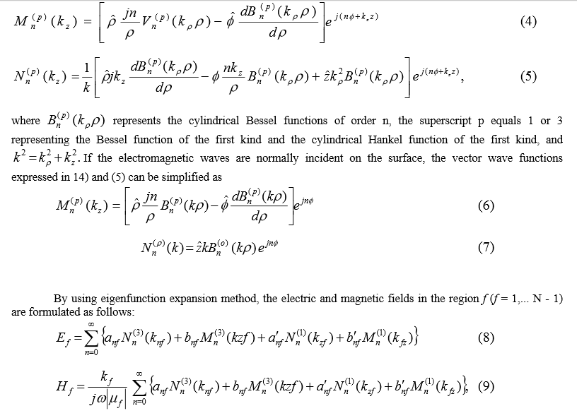
For the incidence wave of transverse magnetic polarization, the reflection visibly diminishes when the electric size of the cylinder is increased. When a parallel line source is placed nearby, focus phenomenon is observed clearly inside the cylinder, provided that the electric si ze of the cylinder is much larger than the wavelength. Finally, distributions of field components are shown to confirm applicability of these formulas. denoted as follows: tj e ω − f f u εε = (1) f f u μμ = (2) where ⎭ ⎬ ⎫ ⎩ ⎨ ⎧ − − material DSP material DNG u ,1 ,1 (3) An incident wave of transverse electric (TE) or transverse magnetic (TM) polarization is assumed to illuminate the layered cylinder in free space at an arbitrary oblique angle. n the cylindrical coordinates system, the vector wave functions are given in [Li et al., 2000), and rewritten as follows |
For the electromagnetic fields in all the regions, we have the same longitudinal wave vector k z because of the phase matching condition, whereas the radial wave vector k pf is discontinuous. In the above formulas, the expansion coefficients, a nf , b nf , a / nf , and b / nf , and can be determined by enforcing the boundary conditions of the tangential electric and magnetic field components on the cylindrical interfaces at p = r f (where f =0,l,...,N-1):
A recursive system for the coefficients ca n be finally obtained [Li et al, 2000]: C f +1 = T f C 1 , (15) where [C f ] is defined by (16) [ ,,, , , T nfnfnfnff BaBaC ′′ the transmission matrix in the eigenexpansion domain is given by , 1 1 fff FFT − + = (17) and the parameter matrices F f and F f+1 are derived from the boundary conditions. Employing the coefficients in the region 0 a nd the Nth region, the scattering coefficients, a no and b no can be derived. With the known a n0 , b n0 , a / n0 ,and b / n0 , in region 0, the scattering coefficients, a nf , b nf , a / nf , and b / nf , in region f can be determined by the recursive relationship as in equa tion (15). Hence the total elect ric and magnetic fields in any region can be found
2.1. Incident TE2 and TM. Waves
The incident TE z and TM z waves, which are expanded in terms of M n and N n , have the following forms: for the TM wave,
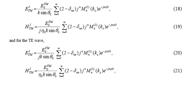
where δ mn = 1 for m = n; or 0 for m ≠ n while the vector wave functions M and N are denoted by equations (4) and (5). Thus a / no and b / no are represented by
2.2.Infinitely Long Line Source
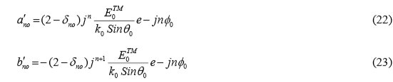
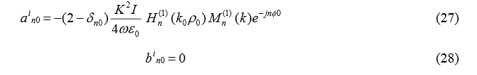
For an infinitely long line source placed at ( ρ 0 φ 0 ) and parallel to the cylinder, the incident electromagnetic wave can be expressed by
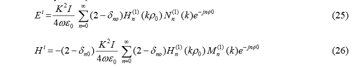
where I stands for the amplitude of el ectric current, P0 denotes the distance from the center of cylinder, and the vector wave functions M and N are denoted by equations (6) and (7). Then, a' no and b' n0 are represented by
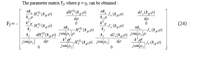
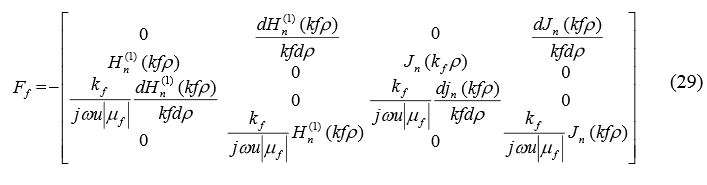
Similarly, F f , where ρ = r f ; can be derived:
3. Numerical Results
To verify the correctness of the formulations deduced above, we first calculate the distant scattering pattern of a two-layered (three regions) cylinder filled with different DPS materials and illuminated by the TE and TM waves, and radiated by the parallel line source, respectively. The geometry is shown in Figure 2. The radii of two layers from inside to outside are a = 0.25 λ and b = 0.3 λ , respectively. The corresponding relative permittivity are ε r1 = 4.0, and ε r2 1.0. The relative permeability of two layers are μ r1 = μ r2 = 1.0. The plane waves are assumed to be at normal incidence. The line source is placed at a distance of ρ 0 = 0.5 λ from the center of the layered cylinder, and an observation angle φ 0 of 0 degree. The distant scattering pattern can be obtained by the asymptotic form of large-argument Hankel f unctions. The results are shown in Figures 3 and 4, respectively. For the reference, the integral equation solutions, which come from Richmond [1965, 1966], are also given. An excellent agreement is observed between the existing solution presented by Richmond [1965, 1966] and those that we newly obtain. This partially verified the correctness of our derived th eoretical formulas and the developed codes. Subsequently, we utilize these formulas to calculate the electromagnetic fields in the presence of the multilayered cylinder filled with DNG and DPS materials. In order to illustrate better the usefulness of these general formulas, the constitutive parameters of DNG materials are specified by (- ε 0, - μ 0 ) and those of DPS materials are ( ε 0 , μ 0 ) in the following computations. The cylindrical interfaces are all depicted by circular curves in the figures. First of all, the normalized scattering cross section σ / μ of a one-layered (two regions) cylinder filled with DNG (- ε 0, - μ 0 ) material is calculated under illumination by the incident TM wave with the angles of θ i = π /2 and φ i = π in the free space. Curves for different radii a of the cylinder are plotted in Figure 5. It is obvious that the reflection by the cylinder is quickly diminished with the increase of the radius. We can also observe that the RCS data at and near φ =0 0 are very large and it is of the impulse shape when the cylindrical radius is large. This phenomenon can be explained as follows. First of all, in Figure 5, the incident wave (a TM- polarized plane wave) is impinged at an angle of elevation θ i = 90° and azimuth φ =180°. In this case, some portion of the wave energy is normally incident upon the cylinder, so the transmitted wave due to this portion propagates entirel y through the dielectric cylinder when the impedance is matched ( ε r = μ r =1) |
|
This portion of waves contributes to part of bistatic RCS datum of φ = 0°. For a cylinder of large radius, illumination area by normal or nearly normal incident waves is larger than that of a cylinder of smaller radius. In this case, the cylinder tends to be a perfectly matched layer and it is almost transparent to the incident wave (especially when the wav is forward propagating). Therefore the percentage of the energy propagated through the cylinder will be relatively larger. Beam width: Secondly, the cylinder behaves as a dielectric lens. For RCS computations, we take the observation point at infinity. When the incident wave propagates through the cylinder filled with DNG, the focus point will appr oach to infinity because of the
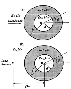
Figure 2. Geometry of a two-layered cylinder with DPS materials.
smoother dielectric curvature. For example, when ka = 100, the observation point (infinity) lies to the right of the focus point (which is already sufficiently far away from origin). Thus it can be imagined that the angle of coverage is small at around φ = 0 0 . When the radius becomes larger and larger, the observation point and the focus point will move closer and closer to each other. In an extreme case, when the cylinder tends to approach a flat slab, the angle of coverage is almost zero to form a delta. That is why the scattering cross sections around the angle of φ = 0 0 . are thus much stronger, but confined within a very narrow angle. |
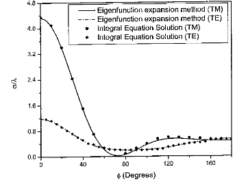
Figure 3. Distant scatteri ng pattern of TE and TM waves illuminating a two-la yered cylinder with DPS materials.
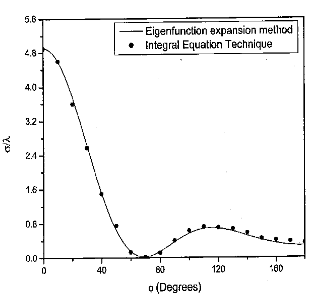
Figure 4. Scattering pattern of a nearby parallel line source in the presence of a two-layered cylinder with DPS materials.
 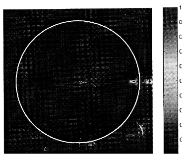
Figure 8. Normalized amplitudes of the time- averaged Poynting power for a one-layered cylinder with (- ε 0, - μ 0 ) and a = 150 λ .
According to the theory, if we keep the wave scattering properties unchanged after the geometrical dimension (e.g., the radius) is changed, we have to adjust μ and ε accordingly. When th e physical problem is changed from a perfect slab lens to a perfect cylindrical lens, the permittivity and permeability in the lens are required to be a function of position. Hence the cylinder with (- ε 0, - μ 0 ) cannot focus the light, and it will still reflect waves. However, a phenomenon of focus shown as in Figure 8 and very small reflection shown as in Figure 5 can be obtained when the electric size of calculated problem is far larger than the wavelength. Finally, the real parts of field components, H ρ , H φ , and E z , scattered by a two-layered (three regions) cylinder filled alternately with DNG and DPS material are shown in Figures 9, 10, and 11. In this case, a line source is placed at ρ 0 = 9.5 λ φ 0 = 0, the radii of two layers are r 1 = 8 λ and r 2 = 5 λ , respectively. The region 0 is the free space, region 1 and 2 are filled with (- ε 0, - μ 0 ) and ( ε 0, μ 0 ) respectively. As we expect, the tangential components H φ and E z are equal on the layered interfaces. While the normal component H ρ is not, which satisfies by default the continuity of normal component of magnetic flux density B across the interfaces between the DNG and DPS materials.
Conclusion
In this paper, we applied the eigenfunction expansion method to generally express the fields in a multi-layered cylinder filled by a double negative 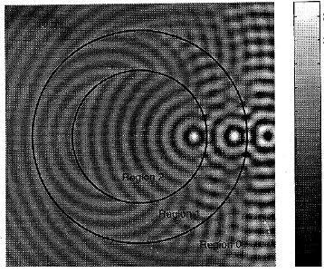
Figure 11. Real part of the E z component of an electromagnetic wave propagating through a two- layered cylinder with DN G and DPS materials.
References
Chen, H. S., L. X. Ran, I. T. Huangfii, X. M. Zhang, K. S. Chen, T. M. Grzegorczyk, and J. A. Kong (2004), Lefthanded materials composed of only S-shaped resonators, Phys. Rev B, 70, 057605.
Grbic, A., and G. V. Elefthcriades (2004), Overcoming the diffraction timit with a planar left-handed transmission-line lens, PIi,w. Rev. Lea., 92, 117403.
Katsarakis, N., T. Koschny, M. Kafesaki, F. N. Economou, F. Ozbay, and C. M. Soukoulis (2004), Left- and right-handed transmission peaks near the ma gnetic resonance frequency in composite metamaterials, Phvs. Rev. B, 70, 201101.
Kong, J. A. (2002), Electromagn etic wave interaction with sun- titled negative isotropic media, Frog. Electromogn. Res., 35, 1-52.
Kuzmiak, V., and A. A. Ma radudin (2002), Scattering proprtties of a cylinder fabricat ed from a left-h anded material, Fhvs. Rev B, 66, 045116.
Li, L. W., D. You, M. S. Leong, and T. S. Yeo (2000), Electromagnetic scattering by multilayered chiral-media structures: A scattering-to-radiation transform, Frog. Electromagn. Res., 26, 249 - 291.
Markos. P., and C. M. Soukoul is (2002), Numerical studies of left-handed materials and arrays of split ring resonators, Phys. Rei E., 65, 036622.
Panoiu, N. C., and R. M. Osgood (2003), Influence of the dispersive properties of metals on the transmission characteristics of left-handed materials, Phys. Rev. E, 68, 016611 |
|
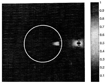
Figure 6. Normalized amplitudes of the time- averaged Poynting power for a one-layered cylinder with (- ε 0, - μ 0 ) and a = 2.5 λ .
Then, radiation by a line source in the presence of this cylinder is considered. The different radii for a values are also set. The line source is located at ρ t 2.3 λ and φ 0 = 0, where p is the distance from the surface of the cylinder. The normalized amplitudes of the time- averaged Poynting power, which is denoted by ⟨ S ⟩ = are shown in Figures 6, 7, and 8. From Figures 6 and 7, we observe that a facula is formed inside the cylinder. The form ation of the facula is due to the cylinder with (- ε *)(Re 1 2 HE × 0, - μ 0 ) is not a focusing system. This summary point can be verified by using the theory of arbitrary coordinate transformations [ Ward and Pendry, (1996)
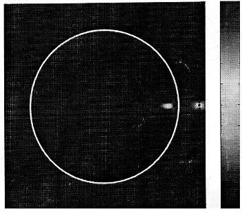
Figure 7. Normalized amplitudes of the time- averaged Poynting power for a one-layered cylinder with (- ε 0, - μ 0 ) and a = 8.5 λ .
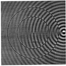
Figure 9. Real part of the H ρ component of an electromagnetic wave pr opagating through a two- layered cylinder with DN G and DPS materials.
medium and a double positive medium. The eigenfunction expansion coeffi cients are determined by enforcing the tangential electric and magnetic field components continuous at the interfaces. By applying the asymptotic form of large- argument Hankel functions, the distant or far-zone scattering patterns for a one-layered cylinder with left (- ε 0, - μ 0 ) and different radii are obtained. The results show that the reflection is vanished with the increasing radius. Moreover, the imaging of a line source by this cylinder is observed when the radius r » λ Finally, field components for a two-layered cylinder altern ately filled with DNG and DPS materials are calculated. The normal component is found to be discontinuous at the boundaries, and the tangential components are not, which agrees, as expected, with the boundary conditions.
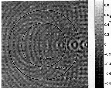
Figure 10. Real part of the H φ component of an electromagnetic wave pr opagating through a two- layered cylinder with DN G and DPS materials.
Pendry, J. B. (2000), Negative refraction makes a perfect lens. Phys. Re: Lett., 85, 3966 - 3969.
Pendry, J. B. (2003), Perfect cylindrical lenses, Optics Express, 11(7), 755 760.
Pendry, J. B., and S. A. Ra makrishna (2003), Focusing light using negative refraction. Z. Phy. B. condens . Alatter, 15, 6345 6364.
Ramakrishna, S. A., and J. B. Pendiy (2004), Spherical perfect lens: Solutions of Maxw ell’s equations for spherical geometry. Phys. Rev B, 69, 115115.
Richmond. J. R. (1965), Scatteri ng by a dielectric cylinder of arbitrary cross-section shape, IEEE Trans. Antennas Propag., 13(3), 334-341.
Richmond, J. R. (1966), TE-wave scattering by a dielectric cylinder of arbitrary cross-section shape, IEEE Trans. Antennas Propag., 14(4), 460 - 464.
Veselago, V. G. (1968), The el ectrodynamics of substances with simultaneously negative values of and i, Soy. Phys. Usp., Engl. Transl., 10(4), 509 514.
Ward, A. J., and J. B. Pendry (1996), Refraction and geometry in Maxwell’s equation, J. Mod. Optics, 43(4), 773 - 793.
Yao, Fl. Y., L. W. Li, Q. Wu, and J. A. Kong (2005a), Macroscopic performance analysis of metamaterials synthesized from microscopic 2-D isotropic cross split-ring resonator array, Frog. Electr ornagn. Res., 51, 197 - 217.
Yao, H. Y., W. Xu, L. W. Li , Q. Wu, and T. S. Yeo (2005b), Propagation property analysis of inetamaterial constructed by conductive SRRs and wires us ing the MGS-based algorithm, IEEE Trans. Microwave Theory Tech., 53(4), 1469- 1476.
Ye, Z. (2003), Optical transmi ssion and reflection of perfect lenses by left handed materi als, Phys. Rev B, 67, 193106.
Zhang, Y., T. M. Grzegorcz yk. and J. A. Kong (2002), Propagation of electromagnetic wa ves in a slab with negative permittivity and negative permeability, Frog. Electromagn. Res., 35, 271 - 286.
Ziolkowski, R. W., and A. D. Kipple (2003), Causality and double-negative metamaterials, Phys. Rev. E, 68, 026615.
|
|