Abstract
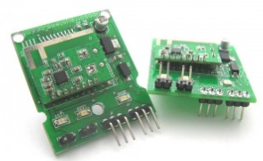
The Paper presents design and development of a CPLD based wireless telecommand system simulating industrial plant automation, wherein master controller remotely controls the relays/ sensors. Transmitting end comprises of RF module and a CPU hosting a LabVIEW based virtual instrument. Front Panel of the virtual instrument consists of 4 switches, few controls to configure COM port and SEND button. Pressing the SEND button would transmit the status of 4 switches through RF module, interfaced to PC through COM port.
Receiving end comprises of RF module and a CPLD development kit. CPLD hosts VHDL code to receive the transmitted string, decode the command and display the command on the LEDs/ monitor and operate a relay
Keywords —CPLD, RF module, LabVIEW based virtual instrument.
I. INTRODUCTION:
In an automated plant, there are number of parameters of various systems, located in different and distant places, which are sensed by variety of sensors, periodically/ continuously, and the data/ status of these parameters is transmitted regularly to the master station. Master station gathers the information from sensors from the entire plant and takes various decisions to control various actuators, which also are spread across the entire pl ant. So, based on the feedback from the sensors, it sends signals to various actuators so that they can switch ON/OFF the valves, initiate alarms, etc.
The transfer of information from the sensing and control units to the master and vice versa takes place through cables laid acro ss the entire plant, or in some cases it happens through wireless channel.
This paper simulates this plant automation in a very basic manner. Subsequent sections will explain the functionality and features which have been implemented in the system.
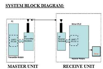
A. Master Unit
The Master unit is simulated as Master controller and the various commands are issued from this unit. Entire unit is implemented in software, which is developed using LabVIEW. A user friendly Graphical User interface is provided for the operator. Master Unit either takes data from the sensors or control buttons on the front panel. Since, no ADC card is used, analog input signal from the sensor is simulated. Usually sensors, after signal conditioning, have voltage outputs ranging from 0 to 10 V and some control signal, which will switch ON/OFF some device, is also issued based upon the signal output. So, a random number generator along with a multiplier is used to simulate the sensor output. And a comparator is used to compare multiplier output against the user defined threshold. Based upon the output of the comparator, a message string is transmitted to the receiver.
Another form of input at the master unit are the control buttons. To simulate this, three switches are provided on the GUI. Different message strings are transmitted based on the state of the switches.
Output of this software module is a message string comprising of states of switches/ simulated sensor output. The string is sent to RS232 interface.
Master unit is implemented using National Instruments’ LabVIEW (Laboratory Virtual Instrumentation Enginneering Workbench), a dataflow programming environment.
C. Receive unit
Receive unit comprises of CPLD kit and Solid state relay. CPLD kit is programmed using VHDL. It is programmed to receive data from RS232 port. The received message string is parsed, and depending upon the status messages received, LEDs on the CPLD board are switched ON./OFF using three signals. With one of the status message, voltage output if provided on expansion pin terminals.
TABLE I
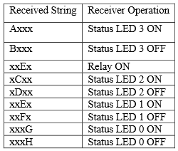
A solid state relay is connected to these pin terminals. So, depending upon the message received, solid state relay is energized/ de-energised. Hence a device connected in a circuit .having relay ouput terminals in the path, gets switched ON/OFF depeding upon the status of the switch at the MASTER.
Receiver uses Xilinx CPLD Board, Solid state relay. At the relay output, any AC/DC device(conforming to the current rating of the relay contacts) to be controlled, may be connected. Software part has been developed in VHDL as a programming language and result has been demonstrated on Xilinx CPLD kit and relay. The Functional module in the Receiver is The UART (universal asynchronous receiver and transmitter) module and Telecommand
V. REFERENCES:
VI. [1] Implementing a Bidirectional Wireless UART Application With TRF6903 and MSP430 Application Report By: Harsha Rao Texas Instruments
[2] Laboratory Reference Manual for Wireless Communication from IIT Delhi.
[3] Application Notes from
www.xilinx.com
www.model.com |