ISSN No: ISSN 0974 – 6331

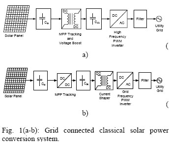
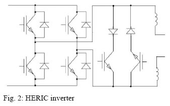
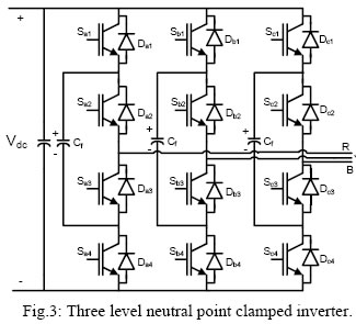
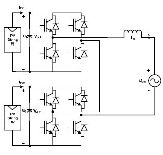
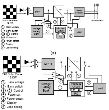
Ranjan K. BeheraRanjan K. Behera Department of Electrical Engineering Indian Institute of Technology, Patna, Bihar, India Abstract As the cost of conventional energy sources continues to increase, alternative energy sources continue to gain in popularity beyond expectation and in this way to reduce environmental pollution. Alternative energy sources, such as Photovoltaic (PV) and Fuel Cell (FC), application is increasing day by day to meet the increased electrical load demand. Particularly, in stand-alone power supply system, powering the electrical load requirement and powering more number of electrical grids is one of the up-coming fields. In India especially in Bihar and Orissa, most of the rural areas are disconnected from the main power grid. Mostly it is in an isolated network, where electrical connection is impossible. To meet this power requirement in rural areas, the stand-alone PV system is the best choice. Although PV energy has received considerable attention over the last few decades, due to high installation cost and the low conversion efficiency of PV modules are the major obstacles to using this PV energy source on a large scale. Therefore, several studies are being developed in order to minimize these drawbacks of the existing system. In order to extract the maximum power of the PV array, the classical implementation of the maximum power point tracking (MPPT) in stand-alone systems is generally accomplished by the series connection of a dc–dc converter between the PV array and the load, the energy storage element or with a grid-tie inverter connected to grid. Considering that in the series connection, the dc–dc converter always processes all power generated, the total efficiency of the PV system greatly depends on the efficiency of this series dc–dc converter and grid-tie inverter. In order to improvement the system efficiency and reliability it is necessary to address suitable fault tolerant power electronics converters system for rural electrification. The power electronics converter topology should posses the ability of smart and intelligent load management and can be used for both isolated loads or grid connected system. Introduction With the ever-increasing demand for “green” energy, solar power has drawn a lot of attention by its rapid growth in recent years. It has been reported that worldwide solar system demand is predicted to continue to grow more than 30% annually for the next three years for the following reasons: excess manufacturing capacity has helped push down average photovoltaic (PV) system prices by more than 25%; the ongoing reduction of PV system installation cost; and the positive incentive movement in multiple regions [1]. Most of the isolated lands in India are situated on the hilly area where it is very difficult to install transmission line to those places due to high price and appreciable line loss. It is preferred to install a solar power generator at the consumers end or top of the hill. In these hilly areas there is plenty of sun shine. In fact, among solar generation system, those based on PV is one of the favorable and reliable method of the power generation for small size power module [2]. Due to rapid growth in semiconductor and power electronics technology, photovoltaic (PV) energy is of increasing interest in electrical power applications. The conventional two-stage PV energy conversion system includes a dc/dc converter and a dc/ac inverter that are connected between a PV array and an electrical power system [3]–[4]. The dc/dc converter is used to track the maximum power point of the PV array according to various maximum power-point tracking (MPPT) methods [5]–[7]. The dc/ac inverter is used to produce an output current in phase with the utility voltage and to obtain a unity power factor. However, the cost and efficiency of the two-stage PV energy conversion system are compromised because of the large number of individual devices, i.e., the dc/dc converter, batteries and dc/ac inverter. Hence, a single-stage PV energy conversion system is proposed for rural electricity applications, resulting in smaller physical volume, lower weight, lower cost, and higher efficiency [8], [9]. This paper aims to give an overview on grid connected PV inverters topology for rural electrification and to outline future trends in this rapidly developing technology. The paper is organized as follows. Section II describes solar power converter topology designs and discusses safety aspects concerning transformer less topologies. Section III outlines new developments including new system designs concept and discusses new transformer lesstopologies. Section IV summarizes the main findings and developments Solar Power Converter Topology Power electronics design plays a key role in the performance of a solar power system, as design engineers first look at maximum conversion. Since PV modules have very low conversion efficiency from solar to electrical energy (in the range of 20 percent), the efficiency of a power inverter is meaningful to minimize solar module area and volume of the entire system. Additionally, power loss of devices generates heat on silicon dies that causes temperature rise and must be effectively dissipated. These losses lead to a thermal stress. Hence, a high reliable design of power electronics converter with heat sink is necessary. Minimum power loss not only saves energy, but also enhances system reliability, making the system more compact and less costly. To convert the fluctuating direct current (DC) output voltage from solar modules into a well- regulated sinusoidal alternating current (AC) voltage, the architecture of a typical solar power conversion system is either two-stage or single-stage, with or without, DC/DC converter as shown in Figure-1 (a) and (b). The existence of a DC/DC stage can maintain the input voltage of inverter at a constant and controlled level, and decouple the control of voltage and power flow. However, an extra conversion stage can have a negative effect on system efficiency. Because of this, more solar inverter manufacturers are evaluating and adopting single stage architecture, even when the inverter control is more complicated and voltage rating of power devices can increase. Among the recently introduced inverter topologies, two are considered to have the most potential for grid-tied centralized inverters in the future - HERIC (Sunways) and multilevel inverters. HERIC, shown in Figure 2, is structurally different than a conventional full-bridge inverter, incorporating an extra switch and diode pairs at the output. With these added devices and appropriate control, HERIC inverters are capable of boosting the system efficiency by effectively handling the reactive power flow. Fig.4: Cascaded multilevel inverter Three level Neutral Point Clamped (NPC) and cascaded multilevel Inverter, shown in Figure 3 and Figure 4 is a specialized topology targeted at centralized solar power applications with higher voltages. Compared to its traditional counterpart, these inverters have only one half of voltage stress on each switch so that devices with much lower voltage can be used. This leads to higher efficiency and lower device costs. In addition, the electromagnetic interference (EMI) level and output filter size can be reduced, thus lowering the overall cost of the system. Brief Description of the System
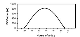
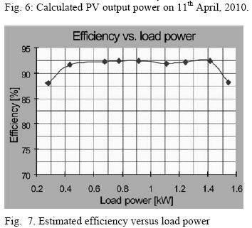
(b) For the load mentioned earlier, (1) gives EPV(min) = 2.29 kW·h. As the load is ac, dividing this value by the efficiency of the inverter (=90%) we get, EPV(min) = 2.54 kW·h. To be on safer side, we have considered this value to be 3 kW·h. In Patna, Bihar, the minimum PV output is produced in the month of December. Using the estimation procedure discussed, it was found that a 1.2 kW panel could produce 3 kW·h/day in December. Hence, it is estimated that nine PV modules having a nominal VOC of 24.0 V and ISC of 7.69 A each. The modules can be connected in series that can produce a peak output of 1296 W at Maximum Power Point (MPP) (Im = 7.2A, Vm = 180 V). Again, it is considered that the ECaSS should be big enough to supply the peak energy even during rainy days. Estimation of PV Output Power Considering the given values of the above parameters, the PV output on a typical sunny day hasbeen estimated and the actual output on the same day has been measured for comparison. The results are presented in Figure 6. Since, the value of ηp is calculated by considering the average temperature of the day, the estimated PPV gives the temperature compensated value. The integrated energy of the estimated PPV is 5.6 kW·h. Although the estimated PV output is smooth, the practically obtained one may have many fluctuations due to the tracking action of the MPPT. However, these fluctuations do not hamper the system operation. As the ECaSS can be charged and discharged quickly, it absorbs these variations and provides a steady output to the power conversion system (PCS). Estimated efficiency versus load power is given in Figure 7. Conclusion
References Corresponding Author:
|
|