|
Analytical Study of Devices for Conversion of Solar Energy into Electrical Energy
K. B. Singh, Baby Sarika, H. L. Sah, A.K. Mishra
Deptt. of Physics, Govt. Polytechnic, Darbhanga, Bihar, India.
& Deptt. of Chemistry, Women’s Polytechnic,patna, Bihar.
University Deptt. of Physics, B.R.A.Bihar University , Muzaffarpur, Bihar
+ P.U.P.College, Motihari, Bihar
e-mail: kbsphysics@yahoo.co.in
Abstract
Energy crisis is the burning problem before the nation. Conventional sources are being exhausted day to day. It is essential to search out the alternative sources of renewable or non-conventional sources of energy of the development of the nation. The present study is concentrated to the different devices useful for conversion of solar energy into electrical power with different conversion efficiencies.
Keywords: Conventional energy, Non-conventional energy, Bio-mass, Nuclear fission.
1. Indroduction
As there is crisis of energy available from conventional sources, which are being consumed at faster rate today, it is useful step for searching out alternative sources of non-conventional or renewable energy. There are many sources of conventional energy such as - (i) Nuclear fission, (ii) Bio-mass, (iii) Wind & (iv) Sun etc. Out of so many sources, Sun is supposed to be the vast ocean of radiation. So it is very much wise step to harness the solar radiation useful for the need of mankind and also for the development of the nation. Whole world today is thinking for the conversion of solar radiation into electrical power due to certain characteristics of the solar radiation. Many countries have developed different devices useful for the conversion of such radiation into electrical power with different amount of conversion efficiencies. These conversion devices are called solar cells, which are categorized as (i) dry solar cell & (ii) wet solar cell.
I. Dry Solar Cells are as follows:
(i) PN jn Si Solar Cell
(ii) Cadmium Sulphide (CdS) solar cells - Thin film solar cell
(iii) Gallium Arsenide (GaAs) solar cell
(iv) Thermoelectric solar cell
(v) Thermo ionic solar cell
(vi) Schottky barrier solar cell.
II. Wet Solar Cell is as follows:
When the load impedance is much smaller than the device impedance. iii)Conversion efficiency (h) & fill factor (FF) - The fill factor (FF) is the ratio of maximum output power to the product of the open circuit voltage and short circuit current. (iv) Materials of desired energy band gap. The performance of of solar cell depends on the material used along with the design of the solar cell.
2.1.P-N Junction Si Solar Cell:
The Si p-n jn. Solar cell serves as a reference device for all solar cells. For satellite and space vehicle flat-plat Si solar cells are the most important long duration power supply. The most widely used and technically developed type of solar cell is the Silicon cell. Its |
|
Photo electrochemical (PEC) solar cell - This PEC solar cell uses different electrode materials such as Tungston Oxide (WO3), TinOxide (SnO2), AlSb, CdS etc.
In this paper we concentrate our study only on the dry Solar cells.
2. Solar Cells:
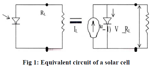
In dry solar cell no any chemical liquid is used. The principle of conversion of solar radiation is based on the laws of photo electricity. Solar cells are (i) photo voltaic, (ii) photo conductive & (iii) photo emission cells. These cells are designed to convert sunlight into electrical power, which is delevered, to a suitable load in an efficient manner. The advantages of these solar cells lie in their ability to provide nearly permanent, uninterrupted power at no operating cost with only heat as a waste product & their conversion of light directly in to electricity. Solar cell consists of semiconductor single crystal or polycrystalline wafer having a very thin diffused region at its surface to form a P-N junction. When light falls on a solar cell then photo voltage develops across the terminal of the solar cell causing an electrical current to flow in the external circuit. (Shown in figure 1).
 . .
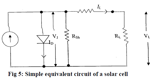
The performance of the cell depends on: (i) Open circuit voltage (Voc) - The open circuit voltage is the output voltage when the load impedance is much greater than the device impedance.
(ii)Short circuit current density (Isc) - The short circuit current density is the output current per unit area popularity stems not from its scientific excellence but from the fact that it builds on the extensive solid-state technology and manufacturing experience of the semiconductor industry. Silicon is chemically stable and yields cells of long lifetime potential in the earth’s environment. Most commercial cells yields 10% conversion efficiency; some now approach 15% in reliable quantities. The silicon solar cell as shown in cross section in fig.2. Single crystal silicon of ultra-high purity is doped through its bulk with arsenic to produce n- type silicon. The surface of a wafer is subsequently doped with boron to produce p-type silicon. This type of cell is called a pn-junction solar cell. One can also reverse the types, yielding an np-junction solar cell. |
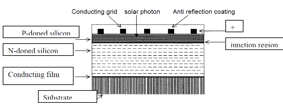 .
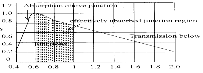
The variation of sensitivity with wavelength for silicon solar cells is determined by a number of competing effects. The extra cutoff in the infrared and the blue can be adjusted in manufacture by varying appropriate physical parameters. The opacity of silicon changes rapidly with wavelength and consequently the depth of placement of the junction below the surfaces of the silicon have much to do with the spectral sensitivity.
Relative resistivity
 .
2.2. Cadmium Sulphide (CdS) Solar Cell
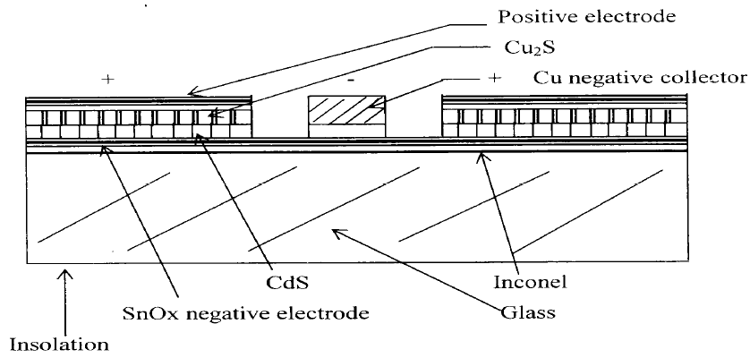
| Next to silicon, the material that has attracted most of the international research effort is cadmium sulphate (CdS), which exhibits the good conversion efficiencies when employed in association wirth copper sulphide (Cu2S) as CdS-Cu2S hetrojunction. In 1974, the commercial production of CdS solar cells was projected for the first time. The technology to be employed is a front wall cell. It consists of a substrate on which a 20 mm thick CdS layer is vaporated with a thin Cu2S film on top of it. The whole is hermetically sealed in a glass encapsulation. Promising development |
|
work is also currently under way on a modified CdS-Cu2S structure whose schematic cross-section shown in fig.3.
The open circuit voltage CdS are in the 400-500 mV range, which is lower than for silicon cell. Short circuit currents comparable to those observed in conventional silicon cells have been reported. The maximum efficiency obtained in the laboratory is between 8% and 8.5 %, but 5% efficiency is more typical of the small production units which have been operated so far. Fig |
 .
2.3. Gallium Arsenide Solar Cell:
The third type of cell, which should be mentioned briefly at this point, is the GaAs solar cell. In the form of polycrystalline form like the presents silicon cells, high conversion efficiencies can be obtained. Efficiencies of 13% have been demonstrated and some source quote 19%. At ground illumination (AMI) the maximum theoretical efficiency is about 27%, higher than for silicon solar cell.
2.4. Thermo Electric Solar Cell
A thermo electric solar cell is one in which a current is generated as the result of the voltage appearing at the junctions of two dissimilar metals. When one set of junction is maintained at a different temperature than the other. The ability of metal to generate this voltage is given by the See beck’s coefficient. Any two metals produce a See beck’s coefficient, but by careful selection one can greatly increase the effect. The cell structure is shown in fig 4.
practical amounts of power can be extracted from the device.
3. Solar Cell equivalent circuit:
By connecting a load across the terminal of a solar cell a current IL can flow through the load and develop a voltage VL and IL, besides depending on the nature of load, will be related to the photo generated current IP and the properties of the diode.
 .
|
|
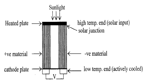 .
2.5.Thermo ionic Solar Cell
Heated metal surface in a vacuum enclosure will emit electrons, forming a space charge about the heated surface. If a second plate of metal at a lower temperature is placed in the same vacuum enclosure, an electric current will flow from the hot to the cold plate. The thermo ionic cell is therefore a vacuum tube designed to accentuate this effect to a point where
The ratio of (ImVm) to (ISC VOC) is defined as the fill factor, which enables a further expression for h to be written as n= (FF.Isc . Voc)/ Pi.a ...........................(2) Where ISC is the maximum possible value of the photo current and VOC is the maximum possible value of photo voltage
Conclusions:
The study of different devices of conversion of solar radiation into electrical power enables us to design and fabricate the inexpensive solar cells. For this purpose attention is to be given to quest the suitable materials available in abundance in nature & conveniently obtained an cheaper rate.
References:
1.S.M. Sze- “Physics of Semi-conductor Devices” Willey Eastern limited, Delhi, 1987. PP 790 to 837.
2.DC Reynold etal-“Photovoltaic Effect in Cadmium Sulphide” phy. Rev 96.533 (1954)
3.C.E. Bookus- “Solar Cell”, IEEE Press, Newyork, 1976.
4.M.P. Jhekaekara-“Data as incident Solar Energy”, Suppl. PROC, 20th Annual Meet, Inst. Environ, see
pP21, 1974 5.K.J. Backmann-“ Material Aspects of Solar Cells”, Current technique in material science, Vol 3. North
Halland, Armesterdam, 1979. 6.M.K. Saran-“ Prepration and Characterization of WO3- PEC solar cell (1984)
7.A. Fuzishumaetal-“Electrochemical Photolysis of water at semiconductor elecrtrode” Nature (London)
37, 2381 (1972) 8.J.F. Kreiders- “Solar Energy Hand book”, IIT Kanpur.
9.H.L.Sah, K.B.Singh et al: "Study of the mechanical, Electrical & magnetic properties pof a SnO PEC Solar Cell" Thesis 2003. |
|